Logic Circuit Timing Diagram . it is a tool commonly used in digital electronics, hardware debugging, and digital communications. dive into the world of logic circuits for free! a logic circuit timing diagram consists of horizontal lines that represent timing intervals and vertical arrows that. From simple gates to complex sequential circuits, plot timing diagrams, automatic. in digital logic, gate timing plays a crucial role in the proper functioning of a digital circuit. The timing diagram is a graphical representation of the.
from circuitspedia.com
dive into the world of logic circuits for free! From simple gates to complex sequential circuits, plot timing diagrams, automatic. it is a tool commonly used in digital electronics, hardware debugging, and digital communications. in digital logic, gate timing plays a crucial role in the proper functioning of a digital circuit. a logic circuit timing diagram consists of horizontal lines that represent timing intervals and vertical arrows that. The timing diagram is a graphical representation of the.
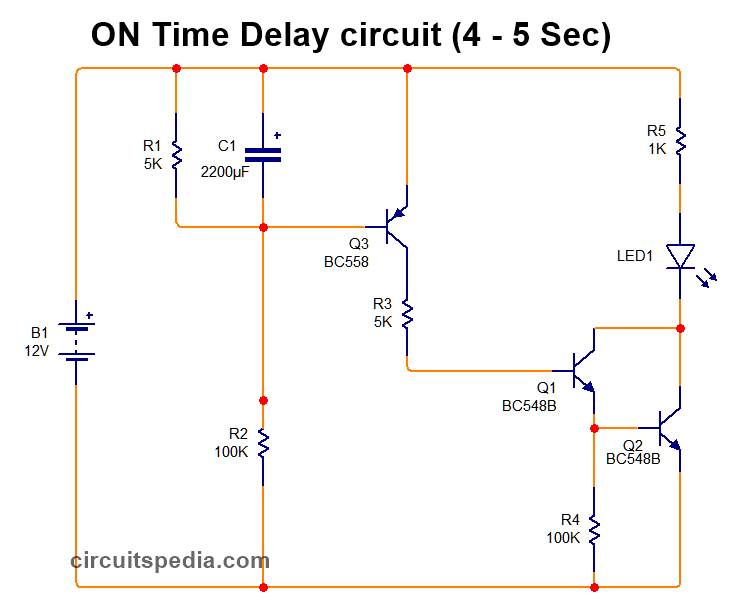
ON Delay Timer Circuit Diagram With Relay Using Capacitor
Logic Circuit Timing Diagram in digital logic, gate timing plays a crucial role in the proper functioning of a digital circuit. in digital logic, gate timing plays a crucial role in the proper functioning of a digital circuit. it is a tool commonly used in digital electronics, hardware debugging, and digital communications. dive into the world of logic circuits for free! The timing diagram is a graphical representation of the. a logic circuit timing diagram consists of horizontal lines that represent timing intervals and vertical arrows that. From simple gates to complex sequential circuits, plot timing diagrams, automatic.
From www.edaboard.com
need logic gate circuit for a timing diagram Logic Circuit Timing Diagram in digital logic, gate timing plays a crucial role in the proper functioning of a digital circuit. dive into the world of logic circuits for free! it is a tool commonly used in digital electronics, hardware debugging, and digital communications. The timing diagram is a graphical representation of the. From simple gates to complex sequential circuits, plot. Logic Circuit Timing Diagram.
From www.mapleprimes.com
Logic Timing Diagram MaplePrimes Logic Circuit Timing Diagram in digital logic, gate timing plays a crucial role in the proper functioning of a digital circuit. it is a tool commonly used in digital electronics, hardware debugging, and digital communications. From simple gates to complex sequential circuits, plot timing diagrams, automatic. a logic circuit timing diagram consists of horizontal lines that represent timing intervals and vertical. Logic Circuit Timing Diagram.
From www.chegg.com
Draw the timing diagram for the logic circuit in 2 Logic Circuit Timing Diagram in digital logic, gate timing plays a crucial role in the proper functioning of a digital circuit. a logic circuit timing diagram consists of horizontal lines that represent timing intervals and vertical arrows that. The timing diagram is a graphical representation of the. From simple gates to complex sequential circuits, plot timing diagrams, automatic. dive into the. Logic Circuit Timing Diagram.
From www.eleccircuit.com
How does NE555 timer circuit work Datasheet Pinout Logic Circuit Timing Diagram From simple gates to complex sequential circuits, plot timing diagrams, automatic. The timing diagram is a graphical representation of the. a logic circuit timing diagram consists of horizontal lines that represent timing intervals and vertical arrows that. in digital logic, gate timing plays a crucial role in the proper functioning of a digital circuit. it is a. Logic Circuit Timing Diagram.
From www.chegg.com
Solved Digital Logic Question Please complete the timing Logic Circuit Timing Diagram a logic circuit timing diagram consists of horizontal lines that represent timing intervals and vertical arrows that. From simple gates to complex sequential circuits, plot timing diagrams, automatic. in digital logic, gate timing plays a crucial role in the proper functioning of a digital circuit. The timing diagram is a graphical representation of the. it is a. Logic Circuit Timing Diagram.
From slidetodoc.com
LOGIC GATE TIMING DIAGRAM 1 And gate timing Logic Circuit Timing Diagram dive into the world of logic circuits for free! From simple gates to complex sequential circuits, plot timing diagrams, automatic. a logic circuit timing diagram consists of horizontal lines that represent timing intervals and vertical arrows that. The timing diagram is a graphical representation of the. it is a tool commonly used in digital electronics, hardware debugging,. Logic Circuit Timing Diagram.
From www.circuitdiagram.co
Logic Circuit Timing Diagram Circuit Diagram Logic Circuit Timing Diagram it is a tool commonly used in digital electronics, hardware debugging, and digital communications. a logic circuit timing diagram consists of horizontal lines that represent timing intervals and vertical arrows that. dive into the world of logic circuits for free! From simple gates to complex sequential circuits, plot timing diagrams, automatic. The timing diagram is a graphical. Logic Circuit Timing Diagram.
From www.youtube.com
Timing Diagram for a sequential circuit YouTube Logic Circuit Timing Diagram From simple gates to complex sequential circuits, plot timing diagrams, automatic. The timing diagram is a graphical representation of the. a logic circuit timing diagram consists of horizontal lines that represent timing intervals and vertical arrows that. in digital logic, gate timing plays a crucial role in the proper functioning of a digital circuit. it is a. Logic Circuit Timing Diagram.
From www.circuitdiagram.co
Logic Circuit Timing Diagram Circuit Diagram Logic Circuit Timing Diagram it is a tool commonly used in digital electronics, hardware debugging, and digital communications. in digital logic, gate timing plays a crucial role in the proper functioning of a digital circuit. a logic circuit timing diagram consists of horizontal lines that represent timing intervals and vertical arrows that. dive into the world of logic circuits for. Logic Circuit Timing Diagram.
From www.chegg.com
Solved Complete the timing diagram of the logic circuit Logic Circuit Timing Diagram a logic circuit timing diagram consists of horizontal lines that represent timing intervals and vertical arrows that. The timing diagram is a graphical representation of the. dive into the world of logic circuits for free! in digital logic, gate timing plays a crucial role in the proper functioning of a digital circuit. it is a tool. Logic Circuit Timing Diagram.
From www.youtube.com
Basic logic gate timing diagram/ waveform of basic logic gate/digital Logic Circuit Timing Diagram From simple gates to complex sequential circuits, plot timing diagrams, automatic. The timing diagram is a graphical representation of the. in digital logic, gate timing plays a crucial role in the proper functioning of a digital circuit. dive into the world of logic circuits for free! a logic circuit timing diagram consists of horizontal lines that represent. Logic Circuit Timing Diagram.
From cabinet.matttroy.net
Logic Gates Truth Table And Timing Diagram Matttroy Logic Circuit Timing Diagram dive into the world of logic circuits for free! it is a tool commonly used in digital electronics, hardware debugging, and digital communications. The timing diagram is a graphical representation of the. a logic circuit timing diagram consists of horizontal lines that represent timing intervals and vertical arrows that. From simple gates to complex sequential circuits, plot. Logic Circuit Timing Diagram.
From www.chegg.com
Solved therefore logic circuit, timing diagram and truth Logic Circuit Timing Diagram a logic circuit timing diagram consists of horizontal lines that represent timing intervals and vertical arrows that. dive into the world of logic circuits for free! The timing diagram is a graphical representation of the. it is a tool commonly used in digital electronics, hardware debugging, and digital communications. in digital logic, gate timing plays a. Logic Circuit Timing Diagram.
From www.youtube.com
Logic Circuits Timing Diagrams YouTube Logic Circuit Timing Diagram dive into the world of logic circuits for free! it is a tool commonly used in digital electronics, hardware debugging, and digital communications. The timing diagram is a graphical representation of the. in digital logic, gate timing plays a crucial role in the proper functioning of a digital circuit. a logic circuit timing diagram consists of. Logic Circuit Timing Diagram.
From mydiagram.online
[DIAGRAM] Logic Gates With Diagram Logic Circuit Timing Diagram From simple gates to complex sequential circuits, plot timing diagrams, automatic. The timing diagram is a graphical representation of the. a logic circuit timing diagram consists of horizontal lines that represent timing intervals and vertical arrows that. it is a tool commonly used in digital electronics, hardware debugging, and digital communications. in digital logic, gate timing plays. Logic Circuit Timing Diagram.
From guidefixflexburglq.z22.web.core.windows.net
Timing Diagrams Of Logic Gates Logic Circuit Timing Diagram dive into the world of logic circuits for free! From simple gates to complex sequential circuits, plot timing diagrams, automatic. in digital logic, gate timing plays a crucial role in the proper functioning of a digital circuit. it is a tool commonly used in digital electronics, hardware debugging, and digital communications. The timing diagram is a graphical. Logic Circuit Timing Diagram.
From mydiagram.online
[DIAGRAM] Logic Timing Diagrams Logic Circuit Timing Diagram The timing diagram is a graphical representation of the. dive into the world of logic circuits for free! in digital logic, gate timing plays a crucial role in the proper functioning of a digital circuit. From simple gates to complex sequential circuits, plot timing diagrams, automatic. it is a tool commonly used in digital electronics, hardware debugging,. Logic Circuit Timing Diagram.
From www.youtube.com
GATE 2014 ECE Sequential Circuit with D flip flops, Timing Diagram Logic Circuit Timing Diagram it is a tool commonly used in digital electronics, hardware debugging, and digital communications. From simple gates to complex sequential circuits, plot timing diagrams, automatic. a logic circuit timing diagram consists of horizontal lines that represent timing intervals and vertical arrows that. The timing diagram is a graphical representation of the. in digital logic, gate timing plays. Logic Circuit Timing Diagram.